Analog sensor integration with PLCs faces common issues. Unlike digital switches, wiring requires specific loop knowledge. Our guide covers principles to troubleshooting.
When the analog output inductive proximity sensor is integrated into the PLC or control system, it is more common in practice if technical difficulties are encountered. The wiring and configuration of the analog output inductive proximity sensor require a specific understanding of the voltage and current loops, which is different from the standard digital switch sensors. Gtric will give you a comprehensive understanding of the analog output inductive proximity sensor, from basic wire working principles to installation best practices and troubleshooting tips.
Why Choose Analog Over Discrete?
The standard inductive sensor is suitable for counting or verifying the closed state. However, if you need to measure how far the machine parts move, or verify the thickness of the metal plate, you need an analog output inductive proximity sensor.
Analog output inductive proximity sensors typically generate one of the following two types of output signals:
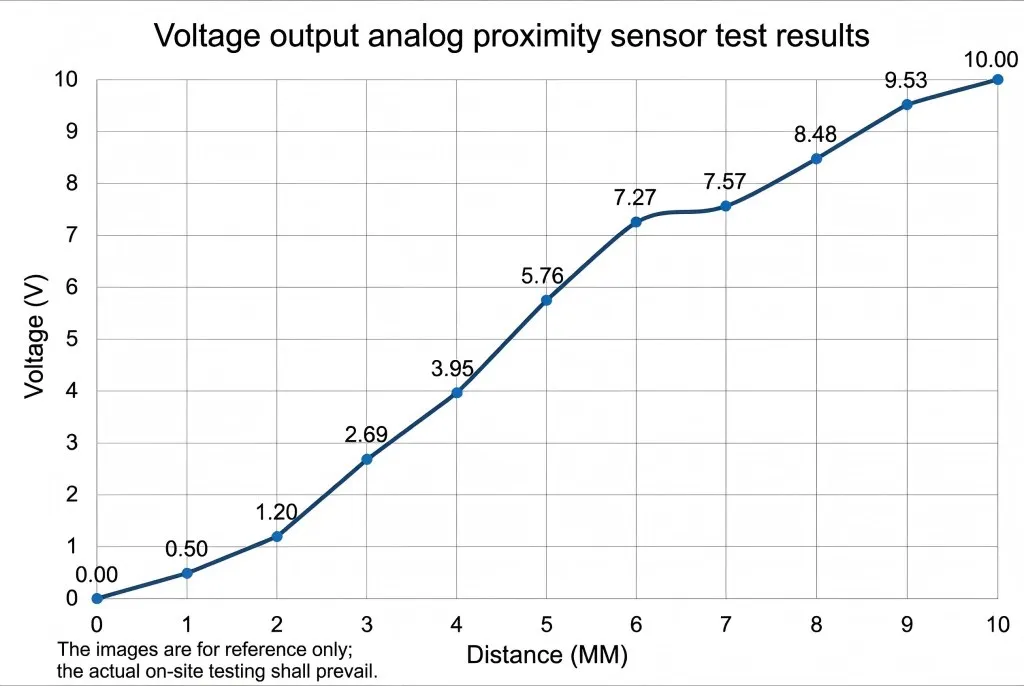
Voltage output (0-10V): Easy to use voltmeter measurement, but vulnerable to electrical noise interference in long cable transmission.
Current Output (4-20mA): Industry standard for long-distance transmission as it is not affected by voltage drop and electrical interference.
How to Connect Your Analog Output Inductive Proximity Sensor
Wiring is usually the most critical step. The error here may damage the expensive analog input module on the sensor or PLC. Please be sure to refer to the specific model of the data table, but usually apply the standard industrial color code (IEC 60947-5-2).
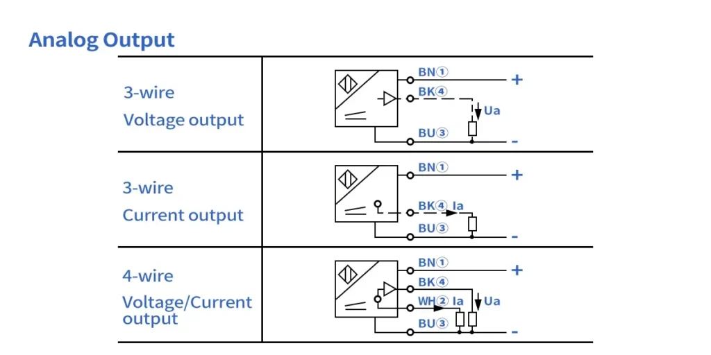
3-wire analog connection
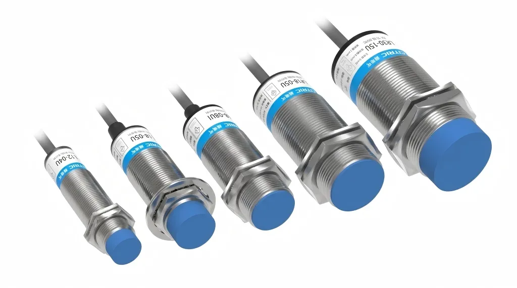
Most modern analog sensors use standard M12 connectors or 3-wire cable tails.
- Brown (BN / Brown): Positive power supply (+ 24V DC usually).
- Blue (BU / Blue): Common ground / negative (0V).
- Black (BK / Black): Analog output signal (connected to PLC analog input +).
- Important Note: PLC analog input (-) terminals are usually connected to the common ground (blue line).
4-wire configuration (voltage and current)
Some multifunctional analog output inductive proximity sensors provide both voltage and current output on the same device.
- Brown: + 24V DC
- Blue: 0V DC
- Black: Voltage output (0-10V)
- White: Current output (4-20mA)
PS: Don’t connect the voltage and current outputs to the same input channel at the same time. Please insulate the unused wire to prevent short circuits.
Best Practices for Step-By-Step Installation
In order to ensure that your analog output inductive proximity sensor has high repeatability and linearity, please follow these mechanical installation rules.
1. Determine the induction range
Analog sensors have a specific linear range. For example, the full range of a sensor may be 0-10mm, but the linear analog range may be only 2-8mm. 2 key areas should be paid attention to when using: the blind area near the induction surface can cause signal instability, while beyond the maximum range, the signal simply clips at its upper or lower limit.
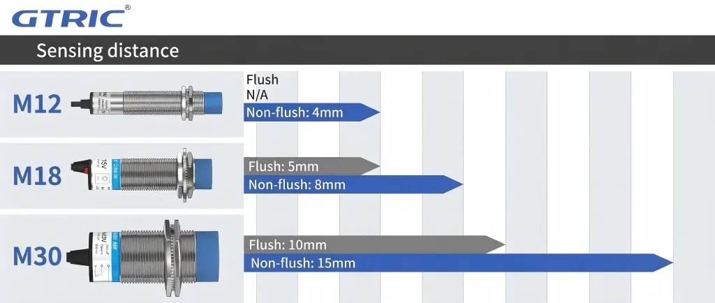
2. Installation and spacing
Inductive sensors are susceptible to interference from surrounding non-target metals, so the installation methods are mainly divided into two types:
- Flush installation (shielding type) allows the sensor to be completely buried in the metal, only the sensing surface is exposed
- Non-flat mounting (unshielded) must leave a metal-free area around the sensing head, which is usually required to be 3 times the diameter of the sensor to ensure normal detection.
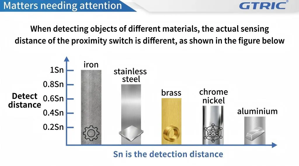
3. Material correction coefficient
The ‘standard’ sensing distance is usually based on low carbon steel (Fe 360). If you are detecting other metals, the effective range of your analog output inductive proximity sensor will be reduced. You can use the following approximate correction coefficients:
- Stainless steel:0.6~0.8 x nominal range
- Brass:0.5~0.6 x nominal range
- Chromium-nickel:0.4~0.5 x nominal range
- Aluminum:0.3~0.4 x nominal range
Configure PLC/Controller
After the physical installation and wiring are completed, you must scale the data in the controller.
Signal scaling (Scaling)
The original values (such as 0 to 32767) collected by the control system need to be converted into the actual distance value in millimeters by linear transformation.
Example formula for 0-10mm sensor (0-10V):
If 0V=0mm and 10V=10m
Troubleshooting Table: Why Does My Sensor Not Work?
If your analog output inductive proximity sensor reading is unstable, check the following common problems before replacing the device:
| The symptoms, factors and solutions of unstable reading of analog output inductive proximity sensor | ||
|---|---|---|
| Symptom | Possible Cause | Solution |
| No Output Signal | Broken wire or power failure. | Check 24V supply on Brown/Blue wires. Verify wiring polarity. |
| Output Stuck at Max | Target is out of range. | Move the target closer. Ensure the target is large enough (std target is square of sensor diameter). |
| Fluctuating Signal | Electrical Noise (EMI). | Use shielded twisted pair cables. Ground the shield at the PLC end only. |
| Non-Linear Readings | Wrong target material. | Aluminum or Copper targets create non-linear curves. Re-calibrate PLC scaling. |
| Drift over Time | Temperature changes. | Ensure ambient temp is within spec. Inductive sensors drift slightly with extreme heat. |
For more information on sensor basics, please see our guide:
Analog Output Inductive Proximity Sensor: The Ultimate Guide
The analog output inductive proximity sensor enables the machine to operate more intelligently, safely, and efficiently by providing real-time distance data. Successful implementation depends on three pillars: selecting the correct sensing range for your material, correctly connecting the analog circuit, and accurately scaling the data in the controller.
Whether you’re building new automation programs or retrofitting older machines to improve accuracy, this guide provides your analog output inductive proximity sensors to operate reliably for years to come.
Can I cut the cable of the analog output inductive proximity sensor?
Yes, but avoid cutting too short. If the cable is shielded, please ensure that the continuity of the shielding layer is maintained to prevent signal noise.
What is the difference between 2-10V and 4-20mA output?
0-10V is a voltage signal, easier to troubleshoot, but vulnerable to noise interference. 4-20mA is a current signal that is more suitable for long-distance transmission and noisy industrial environments.
Does temperature affect the analog output inductive proximity sensor?
The extreme temperature change will cause the switch distance drift. Be sure to check the temperature coefficient in the purchaser’s data sheet.