An In-Depth Look at Principles, Construction, Design, Features, Applications, and Selection Criteria
What is an inductive proximity sensor?
An inductive proximity sensor is a non-contact detection device designed to sense metallic objects within its electromagnetic field. Unlike mechanical switches that wear out from repeated contact or optical sensors that can be blocked by dust, inductive sensors work reliably in harsh industrial environments.
Key points:
- Detects only conductive metals, with optimal performance on ferrous materials like steel.
- Absence of moving parts ensures extended service life and low upkeep.
- Immune to dirt, oil, and most non-metallic contaminants.
| Material | Correction factor (cf) |
| Steel | 1 |
| Copper | 0.25~0.45 |
| Brass | 0.35~0.5 |
| Aluminum | 0.3~0.45 |
| Stainless Steel | 0.6~1 |
| Nickel | 0.65~0.75 |
| Cast iron | 0.9~1.05 |
Example: On an automated conveyor, an inductive sensor can detect the arrival of a steel component at a workstation without touching it, preventing mechanical wear and ensuring precise timing for robotic pick-and-place operations.
Working principles of inductive proximity sensors
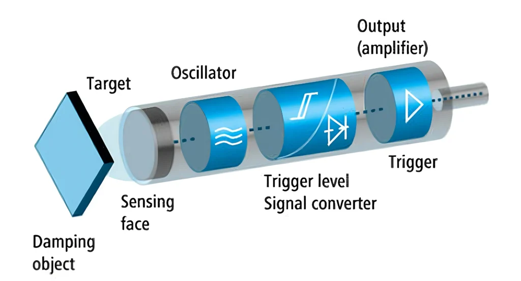
A coil housed in the sensor’s head generates the high-frequency electromagnetic field that enables these devices to operate:
Step-by-step operation:
- The oscillator circuit energizes the coil, producing an oscillating magnetic field at the sensing surface.
- Metallic targets entering this field generate surface eddy currents through induction.
- These eddy currents absorb energy from the oscillator, causing a drop in amplitude.
- The sensor’s detection circuitry recognizes this drop and triggers the output signal.
Analogy: Think of it like tossing stones into still water – where ripples represent the electromagnetic field. A passing boat (the metal object) disrupts the ripples, and the sensor “notices” the disturbance.
Case study: A stamping press line in an automotive plant uses inductive sensors to verify that each sheet of steel is correctly positioned before the press cycles. This simple safeguard prevents tool breakage — a failure that could cost thousands of dollars and hours of downtime (Source: IFM Electronic Application Notes).
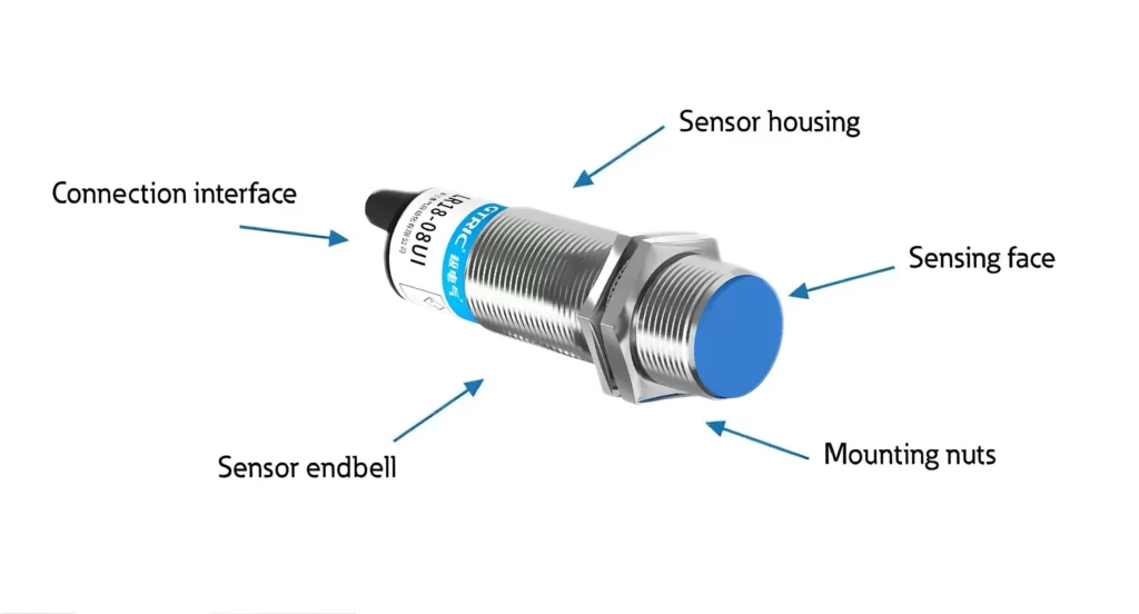
Construction of inductive proximity sensors
While designs differ slightly among manufacturers, most inductive sensors share the same core components:
- Sensing coil – Generates the electromagnetic field.
- Oscillator – Powers the coil at a set high frequency.
- Detector circuit – Monitors changes in oscillation amplitude.
- Output stage – Interfaces with the control system, e.g., a PLC.
- Housing – Often stainless steel or industrial-grade plastic, shaped as cylindrical (M8, M12, M18, M30) or rectangular units.
Installation tip: Shielded (flush-mount) models can be installed level with a metal surface without false triggers, but have a shorter sensing range. Unshielded variants provide greater detection distances but require lateral clearance to prevent false triggers.
Design of inductive proximity sensors
When selecting or designing an inductive sensor for a machine, engineers weigh multiple factors:
- Operating range: Generally 1–40 mm, dependent on sensor dimensions and target metal type.
- Housing style: Flush for compact installations, non-flush for longer range.
- Output type: NPN or PNP for digital switching, or analog for continuous measurement.
- Environmental rating: IP67 or higher for dusty or wet conditions; IP69K for washdown zones.
- Operating temperature: Standard range is -25°C to +70°C, with specialty models for extreme environments.
Example: In a dairy plant, IP69K-rated inductive sensors are mounted on stainless steel filling machines. They withstand daily high-pressure washdowns without corrosion or water ingress, maintaining consistent detection for years.
Features and limitations of inductive proximity sensors
Features:
- Elimination of physical contact prevents component degradation, guaranteeing sustained performance.
- Resistant to dirt, oil, and mechanical vibration.
- High switching precision and repeatability.
- Fast response time, ideal for high-speed automation.
Limitations:
- Detects only metallic targets; non-ferrous metals (e.g., aluminum, brass) reduce sensing range to ~60–80% of rated value.
- Shorter sensing distances compared to ultrasonic or optical sensors.
- Susceptible to strong electromagnetic interference if not properly shielded.
What is a capacitive proximity sensor used for?
Capacitive proximity sensors detect both metallic and non-metallic objects by measuring changes in the capacitance between the sensor’s electrode and the target. This allows them to sense plastics, glass, liquids, powders, and more.
Applications:
- Monitoring plastic pellets in hopper feeders.
- Detecting liquid levels through non-metallic tank walls.
- Sensing cardboard or paper stacks in packaging lines.
Example: In beverage bottling, a capacitive sensor can detect whether a sealed PET bottle contains liquid — all without opening it, which speeds up quality control and reduces waste.
The Difference between inductive and capacitive proximity sensors
| Feature | Inductive Sensor | Capacitive Sensor |
| Detects | Metals only | Metals and non-metals |
| Sensing principle | Electromagnetic field and eddy current effect | Change in capacitance |
| Best for | Gears, shafts, machine parts | Liquids, plastics, powders, glass, wood |
| Typical range | Shorter (1–40 mm) | Similar or slightly longer |
| Environmental impact | Unaffected by dust/oil | Can be affected by moisture or material buildup |
Switching distance of inductive sensors
Targets beyond the operational range limit may not trigger detection.
Key influencing factors:
- Target material – Steel provides full rated range; aluminum or copper can reduce it by up to 40%.
- Sensor size – Larger diameters generally increase sensing distance.
- Mounting style – Flush mounting slightly reduces range; non-flush increases it.
- Temperature – Significant heat or cold can slightly shift the sensing point.
Practical example:
If a sensor is rated at 10 mm for steel:
- Aluminum targets may be detected at only 6–7 mm.
- Using a non-flush model may extend detection to 12 mm.
Pro tip: Always verify switching distance in the real installation environment — lab specs don’t account for surrounding metal structures, temperature swings, or vibration.